The industry-wide adoption of large-format modules means that solar systems have become bigger than ever, resulting in higher flexibility of the tracker structure and increased susceptibility to wind-induced damage.
Yet, building codes do not consider the aeroelastic effects of winds on solar trackers.
Wind tunnel tests are hence needed to examine the aerodynamic stability of the tracker array under different influencing factors, such as incoming flow conditions, tracking angles, and layouts. These findings will then help solar tracker manufacturers to determine the parameters in the design of the solar tracker structure.
This guide provides information about the importance of wind tunnel tests in assessing the aerodynamic stability of solar tracker systems. Read more to understand more about wind tunnel tests for solar trackers!
1.What does a wind tunnel test entail?
Wind tunnel tests mainly include the rigid pressure test and the full aeroelastic test.
The rigid pressure test determines the system coefficient, torque factor, and Dynamic Amplification Factor (DAF).
Meanwhile, the full aeroelastic test determines the critical wind speed, which occurs when damping is negative.
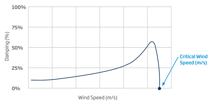
Critical wind speed according to the damping ratio
In the wind tunnel test performed on TrinaTracker’s smart trackers, third-party organizations CPP and RWDI used the tests to define the stow position strategy for its one-in-portrait (1P) trackers and confirm the 2D sectional model test results for its two-in-portrait (2P) trackers.
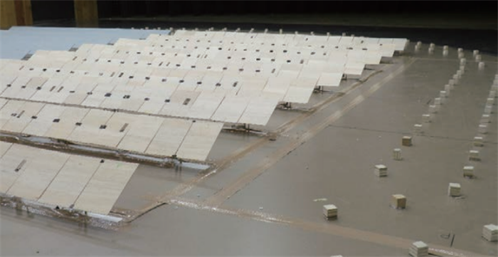
Prototype for full aeroelastic model test
(Source: RWDI Lab)
2.Why are both dynamic and aeroelastic effects important for solar trackers?
Both dynamic and aeroelastic effects can significantly impact the structural design of solar trackers and pose a critical challenge to their safety, stability, and economics.
Dynamic effects have an obvious amplification effect on the equivalent static wind load of flexible structures, and are crucial in the verification of the tracker’s structural strength.
Similarly, aeroelastic effects, such as flutter and vortex vibration, may have destructive effects on the tracker’s structure and must be suppressed or circumvented by certain methods and strategies.
By comparing both, we can get the critical wind speed and ensure a tracker design with maximum stability.
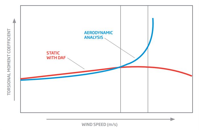
Chart of static torsional and aerodynamic loads showing the different impacts on torsion at different wind speeds.
3.How do you calculate the damping ratios?
Damping ratios can be obtained on-site through free vibration tests or through professional calculation and analysis. TrinaTracker, in collaboration with CPP and RWDI, conducted a professional evaluation of the damping ratio of its Vanguard 1P and Vanguard 2P based on the comprehensive free vibration test results and theoretical analysis calculations.
4.What is the impact of torsional stiffness on tracker stability?
Torsional stiffness is directly proportional to aeroelastic critical wind speed and wind stability. In other words, higher structure torsional stiffness results in higher wind stability.
Therefore, in general, we need to ensure that the torque tube section of the solar tracker has a sufficiently large profile size and thickness. With a series of 120, 130, 150 and 170mm torque tube designs, TrinaTracker allows a comprehensive optimization of safety and cost-effectiveness in the existing wind and snow pressure conditions, of which safety is always of utmost priority.
130mm torque tube
5.Which parameter has the largest impact on tracker stability?
The aerodynamic stability of a solar tracker is mainly determined by damping, stiffness (frequency), and tilt angle of modules; DAF reflects the dynamic amplification effect of the wind load, but not its structural stability.
When the tilt angle is large, solar trackers have relatively good stability. In such scenarios, structural damping can effectively suppress the main aerodynamic issues of vortex vibration and galloping.
At a 0° tilt angle, solar trackers will have relatively poor stability due to flutter. Structural stiffness, or frequency, will then have the largest impact.
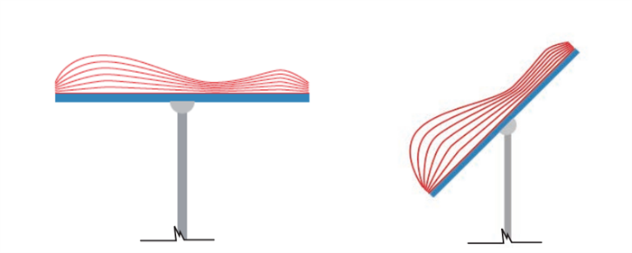
Pressure on modules at low tilt angles (left) and high tilt angles (right)
6.Which wind stow position strategies do the 1P and 2P trackers adopt? How long will it take them to return to the stow angle? What are their strengths and weaknesses compared to their competitors?
Vanguard 1P comes with a single-point drive mechanism. At 0°C, Vanguard 1P has a relatively low aeroelastic critical wind speed and generally adopts a large angle (30°-60°) stow strategy along with bilateral dampers. It returns to the stow angle in no more than 7 minutes (-60° to 30°).
The wind resistance strategy adopted by Vanguard 1P is the best solution for single-drive products in the industry at present, minimizing the effects of flutter that has a destructive effect on the structure. It can effectively suppress vortex shedding and significantly improve the capacity of solar trackers to withstand a hurricane.
The Vanguard 1P’s large tilt angle stow strategy can reduce the load-bearing capacity requirements for the drive system, and simultaneously reduce the snow resistance design requirements for solar trackers. However, the large tilt angle stow strategy has also set very high standards for the design of purlins and pole strength. Thanks to targeted design enhancements and systematic optimization, Vanguard 1P offers the best combination of low cost and high safety.
Meanwhile, Vanguard 2P has a multi-point drive mechanism with sufficient torsional stiffness. It has a sufficiently high aeroelastic critical wind speed at any tilt angle, thus adopting a 0° stow strategy, and returns to the stow angle in no more than 5 minutes (55° to 0°).
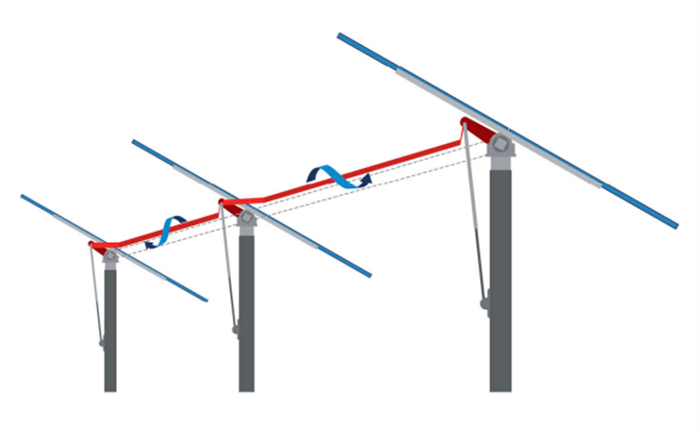
The multi-drive mechanism provides sufficient torsional stiffness and maintains good working conditions under high external loads
The 0° stow strategy adopted by Vanguard 2P can virtually eliminate the impact of horizontal lateral force on poles and foundations and has obvious advantages for high solar trackers. However, the leveling strategy has intensified the requirements on the torsional resistance design of the torque tube and will result in big snow loads on the solar tracker.
7.Can TrinaTracker overcome the harmonic oscillations caused by wind resistance?
TrinaTracker works with two top wind tunnel test labs, CPP and RWDI, for wind tunnel tests. The tests use Agile 1P, Vanguard 1P and Vanguard 2P in single drive, multi-drive; 1P, 2P; single row, double row, and more. Therefore, TrinaTracker has accumulated considerable experience in wind engineering studies for solar trackers of various types and in-depth research into wind-induced vibration effects on trackers; the company is thus more than capable of providing corresponding solutions to overcome the potential risks.
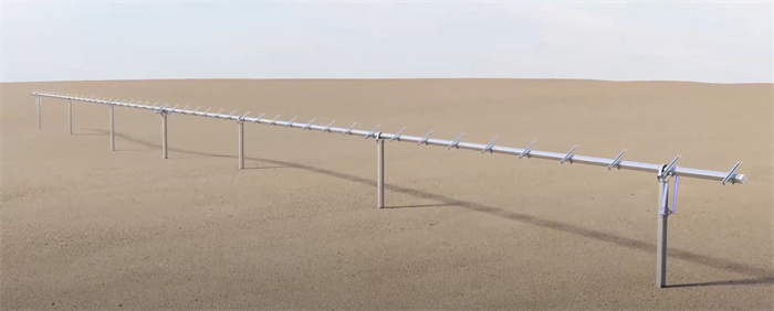
Take Vanguard 1P for example. It is a single-row single-drive 1P product with a length of about 100m. There is a greater risk that Vanguard 1P will have a greater risk of flutter instability when stowed at 10°, which is why the stow angle is larger at 30°, which is when vortex vibration is the main factor contributing to wind-induced vibration instability.
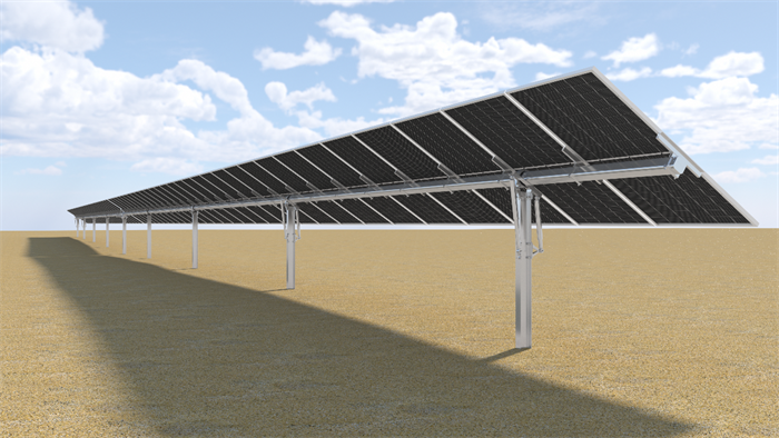
Vanguard 1P solar tracker
Adding the damper is a very effective way to suppress vortex vibration. Therefore, Vanguard 1P comes with bidirectional dampers. The wind tunnel test results from CPP show that Vanguard 1P can reach a critical instability wind speed of up to 60m/s or more at the stow position, which is sufficient to meet the wind resistance requirements for trackers in most areas.
8.Does TrinaTracker perform different tunnel tests to match different site characteristics, particularly for difficult and complex sites?
As part of the overall wind tunnel test, we perform several tilt angle tests and wind direction tests on solar tracker arrays at different locations on a slope with an inclination of 15°. This accounts for different terrains and, at the same time, helps to obtain additional topographic adjustment factors for wind loads.
However, we do not perform wind tunnel tests for individual project sites. Doing so would be costly and time-consuming, and it is not practical to scale down thousands of arrays of trackers and perform wind tunnel tests on all of them. Moreover, structural designs based on the results of existing standard wind tunnel tests are sufficient to ensure the safety of solar tracker systems in terms of wind load.
With that said, TrinaTracker can perform additional computational fluid dynamics simulation studies if needed, but customers need to note that this will significantly increase the project cycle and cost.
9.Has TrinaTracker tested tracker stability in a real project under specific and real wind circumstances?
During the new product development phase, in addition to theoretical calculations and alpha testing, TrinaTracker will also arrange beta tests on a megawatt-level outdoor site, followed by long-term follow-up observations. A new product will only be used in Trina projects after it reaches its plateau phase for more than 6 months.
Additionally, the satisfactory wind resistance performance of our solar tracker structure has been verified by the smooth operation of several existing projects after a long period of observation. For instance, the Vanguard 2P tracker demonstrated its stable and efficient operation in the ±800 kV UHV DC Power Transmission Project in Qinghai-Henan, China, commissioned in 2020.
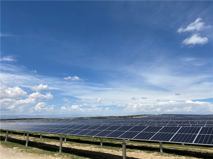
±800 kV UHV DC Power Transmission Project in Qinghai-Henan, China
10.How are modules tested for wind load? What is the maximum module size that current solar trackers can fit?
Wind loads on modules of different sizes can be quantified from wind tunnel tests; when used with purlins, matching tests will be performed on modules.
Current trackers in the market can be matched with large-format modules. Some tracker designs, like TrinaTracker’s smart trackers, are specifically designed to ensure high compatibility with the large-format 210mm-based modules of up to 670W.
11.Is it better to use larger-format 600W+ modules or smaller-format 550W+ modules for high wind/cyclonic zones (basic wind speed: 30m/s, gusts: 50m/s)?
There is often no single ‘best choice’ because each project is different – the best choice for your project will depend on the customer’s requirements and structural design calculations. However, in general, large-format modules will result in a bigger wind load on the solar tracker structure and a higher tracker cost, but a more cost-effective power station in the long run.
When choosing a tracker, you will also need to consider its stability in high wind and cyclonic zones. During the design phase and in wind tunnel tests, TrinaTracker’s tracker products have taken into consideration the compatibility of large-format 210mm modules and can perfectly adapt to the extreme gust wind speed of 50m/s.
Recently, the 1P tracker system was also validated by RINA Tech Renewables, a reputable inspection, certification and consulting multinational organization, for compliance with the Australian Building Codes and Standards for deployment in Wind Region C, which refers to a part of Australia’s northern coastal area where wind speeds are classified as cyclonic and can go as high as 248 km/h.
12.Where can I get specific data of the wind tunnel test?
Wind tunnel data is generally not disclosed to the public as it is considered the core information of the solar tracker manufacturer. Engineers that require wind tunnel data can typically refer to the product’s calculation sheet, which is mainly used for the calculation of wind loads and wind torsion on structural components, and the verification of aeroelastic instability.
Want to learn more? Download the Strategies to Mitigate Risks Associated to Wind Loads in Trackers Compatible with Large-Format Modules White Paper today.